


Calculations for power supplies
Below are bundles of equations and examples to derive the theoretical voltage and current output for many varieties of power supplies. With power supplies - whenever possible, I opt for toroid transformers, configured as voltage doublers. Since toroids generate little heat, they can be well-concealed inside of a chassis. If necessary - to save space and unlike EI transformers, toroids can be stacked - with no fear of electro-magnetic interference. [1]
Diodes
A few words on selecting diodes: a diode must be able to withstand the voltage on and the current passing through it. The minimum Peak Inverse Voltage rating for a diode to be used is:
MinV = 2 * 1.4 * Vac
The minimum Peak Current Rating for a diode is:
MinA = 2 * .7 * Idc
- Given: The AC secondaries of a full-wave rectifier are 300V-0V-300V and the max current draw of the amp is 300ma.
- Problem: What's the minimum voltage and the minimum current rating for a diode to be used in this circuit?
- Solution: MinV = 2 * 1.4 * 300 = 840V
- Solution: MinA = .30A * .7 * 2 = .420A
- Since there are no 840V@420ma diodes manufactured, a 1000V@1A diode is an adequate choice.
Cheap diodes have been rumored to produce a "snap on" spike when they begin a phase of their conduction. An audible noise is alleged to be generated. Soft, fast, ultra-soft and ultra-fast recovery diodes - which dampen the spike, are available at higher prices than the cheap ones (IN400x and 1N540x series). They are advertized by the names of hexfred, Cree, etc. It's unlikely that the fast diodes suppress audible noise, but soft diodes do appear to enhance bass response - significantly.
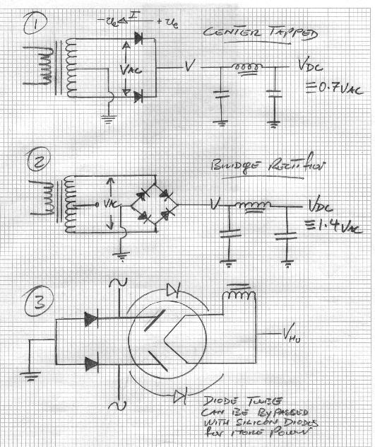
A pervasive anti-diode-fear runs: "Since solid state devices bring up the B+ up instantly, a destructive phenomenon, known as cathode stripping, occurs.". Cathode stripping is alleged to decrease the lifetime of a tube. However - unless high voltages are used (600Vdc and beyond), this fear is largely unfounded. To delay the ramping up of the B+ at high voltages, a hybrid (diodes and tubes) Full wave bridge (FWB) rectifier may be constructed. Here and here are examples of hybrid FWB rectifiers.
From Hammond Manufacturing, here is their "Design Guide for Rectifier Use". It contains a number of equations, devised to calculate the RMS voltage for various power supply configurations, advice for selecting diodes and caps, etc.
Full Wave capacitor input
[For full wave supplies, the AC secondary current rating must be at the minimum 1.2 times DC current draw. 1.2 times required ADC is a limit on how DC current can be produced by a transformer.]
Vac = Vdc * 1.41
Iac = Idc
- Given: A 360-0-360 Vac supply and Vac = Vdc * 1.41 (rearranged to: Vdc = Vac / 1.41).
- Problem: What will the B+ (the high voltage DC) be?
- Solution: Vdc = 720 / 1.41 = 511
- Given: A maximum of 425Vdc and Vac = Vdc * 1.41.
- Problem: What Vac secondary is needed?
- Solution: Vac = 425 * 1.41 = 600
- So, a 300-0-300 Vac power transformer is required.
Full Wave choke input
Vac = Vdc * 2.22
Iac = Idc * 0.65
- Given: You've found a 475-0-475 Vac transformer for dirt-cheap on ebay and Vac = Vdc * 2.22 (rearranged to: Vdc = Vac / 2.22).
- Problem: What DC voltage will it produce after rectification?
- Solution: Vdc = 950 / 2.22 = 428Vdc
- 428Vdc is the recommended voltage at which to run 25W tubes - such as the KT66 and the EL34.
- Given: You require 300ma DC current and Iac = Idc * 0.65.
- Problem: how much AC current is needed from a transformer?
- Solution: Iac = .300 *.65 = .195A = 195ma
- A power transformer which shell-outs 195ma AC can actually produce 300ma DC current with a Full Wave choke input design.
Full Wave bridge capacitor input
[For full wave bridge supplies, the AC secondary current rating must be at the minimum 1.8 times estimated DC current draw.]
Vac = Vdc * 0.71
Iac = Idc * 1.61
- Given: A 500ma Vac supply and Iac = Idc * 1.61 (rearranged to: Idc = Iac / 1.61).
- Problem: How much DC current is available?
- Solution: Idc = .500 / 1.61 = .310A = 310ma
- Given: You need to obtain 500Vdc and Vac = Vdc * 0.71.
- Problem: what Vac transformer is needed?
- Solution: Vac = 500 * .71 = 355
- So, a supply rated at 355-0 Vac is necessary.
Full Wave bridge choke input
Vac = Vdc * 1.11
Iac = Idc * 1.06
- Given: A 575Vac supply and Vac = Vdc * 1.11 (rearranged to: Vdc = Vac / 1.11).
- Problem: How much DC voltage will be produced?
- Solution: Vdc = 575 / 1.11 = 518
- Given: A transformer rated for 600ma AC current and Iac = Idc * 1.06 (rearranged to: Idc = Iac / 1.06).
- Problem: how much DC current is available?
- Solution: Idc = .6 / 1.06 = .566A = 566ma
The above voltage and current produced from a 575Vac@600ma transformer in conjunction with a rarely used choke input design would produce an excellent supply for a PP KT88 stereo amp. Bear this in mind: an expensive choke is required for this type of application. Without a high-quality choke, the supply may prone to produce an annoying buzz.
Voltage doublers
Shown above is a full-wave voltage doubler. In tube amp building, the negative lead is grounded. Only positive voltage is required to energize the plates and screens of the drivers and output tubes. Generally, the only application for negative voltage is when a negative VDC signal is shot into the grid to bias an output tube.
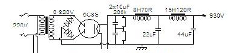
In the schematic below, the juncture - where the filter caps meet - can be tapped off to extract 1/2 of the positive voltage (+465Vdc). This electro-trick is expedient. Dropping 1/2 of the B+ for the drive stage's tubes with resistors is more efficient - than dropping the entire B+ with them.
Eout = (2 * Ein) * 1.414
Iac = 3.6 * Idc
(Eout is a theoretical outcome. Rarely is the theoretical maximum obtained. Plus - when the supply is under load, the B+ measured is lower than when measured with no tubes in. As a rule of thumb, the Eout maximum is 2.8 times Ein.)
- Given: A power transformer whose secondary voltage is 400Vac and Eout = (2 * Ein) * 1.414.
- Problem: What's the theoretical DC voltage output?
- Solution: Eout = (2 * 400) * 1.414 = 1128Vdc
- Given: A transformer rated at 600ma AC and Iac = 3.6 * Idc.
- Problem: What's the maximum DC current available from it?
- Solution: .6A = 3.6 * Idc = Idc = .6A / 3.6 = .17A = 170ma
- Given: A transformer with a 325Vac@.9A rating and Iac = 3.6 * Idc and Eout = (2 * Ein) * 1.414.
- Probem: What's the expected voltage and current yield from this transformer?
- Solution: Eout = (2 * 325) * 1.414 = 919Vdc
- Solution: Idc = .9A / 3.6 = .25A = 250ma
The famous Harman Kardon Citation II employed a doubler with a 180Vac@1.7A power transformer, and the Marantz 8b contained a doubler with a 160Vac@1.2A power transformer.
Turns ratio formulas
Let's look at the turns ratio of one of the center-tapped transformers (360-0-360), mentioned above. Its turns ratio is 1:6 (primary to secondary), and the line voltage attached is 120Vac. What's its secondary AC voltage?
Es / Ep = Ns / Np
Es = voltage induced on the secondary
Ep = voltage applied to the primary
Ns = number of turns in the secondary
Np = number of turns in the primary
Es = Ep * Ns / Np
Es = 120 * 6 / 1 = 720 = 360-0-360
The Total VA of a power transformer
(E * I) + (E * I) + (E * I) + {....} = VA
When a custom power transformer is ordered, it's often necessary to specify the Total VA. Suppose that we request an order for a power transformer with the following characteristics:
winding 1 = 360-0-360 @ 500ma
winding 2 = 3.15-0-3.15 @ 5A
winding 3 = 3.15-0-3.15 @ 5A
winding 4 = 5V @ 4A
What's the VA of the above transformer?
(360 * 2) * .500 + (3.15 * 2) * 5 + (3.15 * 2) * 5 + (5 * 1) * 4 =
720 *.500 (360) + 6.3 * 5 (31.5) + 6.3 * 5 (31.5) + 5 * 4 (20) =
360 + 31.5 + 31.5 + 20 = 443VA
Minimum filter capacitance
- C = W / E^2
- the minimum capacitance in Farads equals the output power of the amplifier divided by the square of the B+ voltage
- Given: A 35W stereo amp - where W = 35 * 2 and E = 425Vdc.
- Problem: What's C?
- Solution: C = 70 / 180625 = 0.00039 F = 390 uF
Most older (EL34, KT66, etc.) amp designs contained nowhere near the above, recommended minimum filter capacitance. One reason was that the first cap, following the rectifier tube, needed a relatively small (8-50uF) value, so as not to stress the tube beyond its current limit. Today - with solid state rectifiers, this concern is largely moot.
However - when large capacitances are used, there's a definite risk of a "voltage doubling effect" should the amplifier be switched off then back on again - in a short period of time (less than a minute). The resulting surge could exceed the maximum voltage rating of the filter capacitors, frying them. To make the filter caps discharge quickly (within 10 seconds), a 5W 220k bleeder resistor should be placed before the first cap in the supply from the high voltage to ground.
- footnote
- 1. In the diagrams for the Full Wave power supplies, look at the center taps. You may use a center-tapped power transformer to create a Full Wave bridge or a voltage doubler, but you must let the center tap "float"; that is, tape or cut off the center tap. Never let it touch ground, or all of the current the transformer has will rush to ground, blowing a fuse or worse.