


Basic math
Immediately following are equations for calculating cathode voltages, currents and resistances. [1]
- Ik = Ek / Rk
- cathode current equals cathode voltage divided by cathode resistor value
(Remember to convert milliamps (ma) to amps (A) by dividing ma by 1000.)
- Given: The cathode voltage is 22.5V and the cathode resistor is 390ohm.
- Problem: What's the cathode current?
- Solution: Ik = 22.5V / 390ohm = .0576A = 58ma
- Given: The cathode voltage is 20 and the intended bias of a tube is 40ma.
- Problem: What value cathode bias resistor is needed?
- Solution: Rk = 20 / .04 = 500ohm
- Given: The cathode bias resistor is 140ohm and the current 48ma.
- Problem: What's the expected cathode voltage?
- Solution: Ek = .048 * 140 = 6.7V
- Pd = Ep * Ik
- plate dissipation equals plate voltage multiplied by cathode current
- Given: The plate voltage is 450V and the (idle) cathode current is 50ma.
- Problem: What is the plate dissipation at idle?
- Solution: Pd = 450V * .050A = 22.5W
Regarding a 25W tube, 22.5W is 90% of its maximum rated Pd. According to Patrick Turner, a PP amp's idle cathode bias - for optimal balance of both tube longevity and power output - should be set at 66% of its maximum Pd. However, many amps (as examples: the Dynaco ST-70 and the Leak TL/25+) were designed to run their output tubes higher than 66% of their maximum Pd.
Transconductance
The transconductance (gm) of a tube is the ratio of a change in AC plate current to a change in AC grid voltage - given a constant plate voltage. In older books, the unit for transconductance is given as "mho" (ohm spelled backwards), where 1 mho = 1 ampere per volt. (In datasheets, gm is represented in µmhos, where µmho = 1 millionth of a mho.) Today, gm is sometimes expressed in Siemens (S), where 1 Siemens = 1 ampere per volt. Below is the formula:
- gm = dIp / dEg
- transconductance equals a small change in plate current divided by a small change in grid voltage
Problem: let's shoot a small AC voltage through the grid of a tube, then measure the AC output current on the plate connected from a resistor to a constant DC voltage source. The current will be controlled by placing a constant current source (CCS) in the cathode circuit.
Given that a 100 mV AC signal is shot through the grid, that a 100ohm resistor is connected to the plate and that 10 mV is measured across the resistor, what is the transconductance of the tube? (Remember to convert millivolts (mV) to volts (V) by dividing mV by 1000.) [2]
I = E / R
Ip = 10 mV (.01V) / 100 = .00001A
gm = dIp / dEg
gm = .00001A / .1V = .001 A / V = 1 mS = 1000 µmhos
Here is a transconductance unit converter.
Below (in µmhos) is a gm list for some (once or currently) popular power tubes:
| 211 | 2A3 | 300B | 6HV5A |
|---|---|---|---|
| 3150 | 5200 | 5400 | 65000 |
| 6L6 | 807 | 813 | 8417 |
| 6000 | 6000 | 3750 | 23000 |
| EL34 | EL84 | GM70 | KT66 |
| 12000 | 11000 | 6000 | 7000 |
| 6146B | 845 | KT88 | 6L6GC |
| 7000 | 3100 | 12000 | 4700 |
mu
Related proportionately to transconductance, mu is the gain in AC plate voltage due to a change in AC grid voltage - given a constant plate current. mu has no unit of measurement. It's expressed as a pure number - often referred to as the amplification factor of a tube.
- mu = dEp / dEg
- mu equals a small change in plate voltage divided by a small change in grid voltage
Let's shoot another AC voltage signal (100 mV) at the grid, then measure the resulting AC voltage on the plate. (The plate needs to be connected to a high impedance load for the results to be accurate.) With 100 mV AC on the grid and a mu of 20, what is the voltage on the plate?
Ep = mu * Eg
Ep = 20 * .1 = 2V
Below is a mu list for (once or currently) popular power tubes. (Pentodes and tetrodes are strapped as triodes to derive their amplification factors):
| 211 | 2A3 | 300B | 6HV5A |
|---|---|---|---|
| 12 | 4.2 | 3.9 | 300 |
| 6L6 | 807 | 813 | 8417 |
| 8 | 8 | 8.5 | 16.5 |
| EL34 | EL84 | GM70 | KT66 |
| 10.5 | 19.5 | 6.7 | 10 |
| 6146B | 845 | KT88 | 6L6GC |
| 4.5 | 5.3 | 8 | 8 |
Rip, gm and mu
Internal plate resistance (Rip) is associated with gm and mu. By definition:
- Rip = dEp / dIp
- Rip equals the AC voltage on the plate divided by the AC current traveling through the plate
- mu = gm * Rip
- mu equals transconductance times internal plate resistance
Here is an example from a GEC KT66 datasheet. IMPORTANT: to make the mu calculation below, find the Rip of a pentode or tetrode - when it's operating as a triode. Given a KT66 in triode mode with the following characteristics:
Ep = 250
Eg1 = -15
gm = 7.3 mA / V
Rip = 1.3k
What is the mu?
mu = .0073 * 1300 = 10
From an EL34 datasheet (in which an EL34 is strapped as a triode), the mu is 10.5 and the gm is 11.5 mA / V, what is its internal plate resistance?
Rip = mu / gm
Rip = 10.5 / .0115 = 913
Below is a list of approximate internal plate resistances (in ohms) for a select set of power tubes. Insofar as pentodes and tetrodes, the internal plate resistances are given - as strapped as triodes.
| 211 | 2A3 | 300B | 6HV5A |
|---|---|---|---|
| 3800 | 800 | 750 | 6400 |
| 6L6 | 807 | 813 | 8417 |
| 1700 | 1700 | 2267 | 717 |
| EL34 | EL84 | GM70 | KT66 |
| 910 | 2000 | 1117 | 1.3k |
| 6146B | 845 | KT88 | 6L6GC |
| 643 | 1700 | 670 | 1700 |
A triode volt amp
Below is a very simple (triode) circuit, used as the input stage of many amps. Much of the analysis and math has been - intentionally - left out, such as input and output impedance, frequency response, etc. - in order to concentrate on the essentials above: mu, gm and Rip.
The voltage gain (Av) is given by:
Av = (mu * Rep) / (Rep + Rip)
From the RCA 6SN7GT datasheet:
Ep = 250
Rep (external plate resistor) = 40k
Rip (internal plate resistance) = 7700
gm = 2600 µmhos
mu = 0.0026 * 7700 = 20
What is the Av?
Av = 20 * 40000 / 40000 + 7700 = 800000 / 47700 = 17
Pentode volt amps
Since a pentode has a screen grid to contend with, calculating voltage gain with it is slightly different - than with a triode. In the datasheets - where the mu is given, the mu of a pentode is derived by strapping the screen to the plate (to make a triode), so the (given) mu will produce erroneous pentode voltage gain estimates. Instead, we'll use the gm. Also, note the internal plate resistances of pentodes (> 100k for pentodes vs. < 10k for triodes). The formula for calculating pentode voltage gain follows.
Av = gm * Rip * Rep / 1000000 * (Rip + Rep)
From the C3m datasheet:
Ep = 225
Eg2 = 155
gm = 6500 µmhos
Rip (internal plate resistance) = 250k
Rep (external plate resistor) = 7.5k
What is the Av?
Av = 6500 * 250000 * 7500 / 1000000 * (250000 + 7500)
Av = 12187500000000 / 257500000000 = 47
With a 12.5k external plate resistor in this C3m circuit, the voltage gain becomes a whopping 77 - yet the circuit does produce an acceptable level of distortion.
Another example of a pentode volt amp with the high gm 12HG7:
Ep = 250
Eg2 = 150
gm = 32000 µmhos
Rip = 60000
Rep = 4000
What is the Av?
Av = 32000 * 60000 * 4000 / 1000000 * 60000 + 4000
Av = 7680000000000 / 64000000000 = 120
Parallel triodes
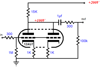
In the diagram above - with the 12au7, two sections of a dual triode can be paralleled by strapping their grids and plates together. Paralleling triodes doubles the transconductance and halves the (internal) plate resistance - relative to a single triode section, but the mu remains the same. The noise performance improves significantly (though it does not double in improvement over a single triode). The cathode and plate resistor values used in parallel triode circuits are - approximately - one half of those in a single triode section.
From an RCA 12AU7A datasheet:
gm = 3100 µmhos
Rip = 6250 ohms
mu = 19.5
Below, the gm and Rp for parallel 12au7 sections:
gm = 2 * 3100 = 6200 µmhos = .0062 mhos
Rip = 6250 / 2 = 3125 ohms
But, why does mu remain the same?
mu = gm * Rip
mu = (2 * .0062) * (6250 / 2) = 19375000 = 19.4
In the above circuit, calculate the voltage gain (AV):
Av = (19.5 * 15000) / (15000 + 3125)
Av = 292500 / 18125 = 16
The voltage gain, like mu, is identical for parallel sections, as with a single section - as long as the plate and cathode resistors used are dropped by half in the circuit.
Cathode Follower
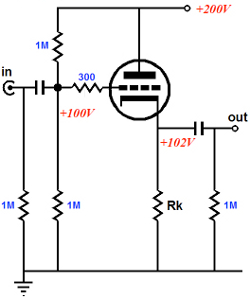
The output impedance of a stage is indirectly proportional to its ability to drive a following stage. (The lower the Zout of one stage, the more of the signal makes it through to the next.) A cathode follower is used, where a low impedance output source is needed to drive a high impedance stage, such as an output tube. An increasing in voltage input signal causes the plate current to rise, which increases the voltage across the cathode resistor, making the cathode more positive with respect to ground. When the input increases the grid-to-ground voltage by 1 volt, the increase in plate current raises the cathode-to-ground voltage by about 1 volt, leaving the grid-to-cathode voltage virtually unchanged. As the grid voltage increases, the cathode voltage "follows". Hence, the circuit's name.
Zout = Rip / mu
From the RCA 12au7 datasheet, what is the output impedance of a 12au7 cathode follower?
mu = 19.5
Rip = 6250 ohms
Zout = 6250 / 19.5 = 320 ohms
Av = mu / (mu + 1)
Cathode followers are, generally, used as buffers - to isolate one stage from another, so their gain is less than unity. The gain for the above circuit is:
Av = 19.5 / (19.5 + 1) = 0.95
Here is a PDF link to the original Ongaku schematic. Notice the cathode follower feeding the 211?
Long Tail Pair
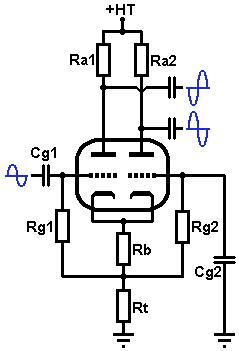
Used in Push Pull amps to control the phases the output tubes receive, the long tail pair is a differential amplifier: an increase in the phase inverter's input voltage decreases the inverted output's voltage but raises the non-inverted output voltage. As the input signal voltage rises, the plate current in the left (inverted) section of the dual triode increases, causing the inverted output voltage to decrease - due to a higher voltage drop across the left plate resistor (Ra1). This also causes the current through the cathode resistor (Rb) and the tail resistor (Rt) to rise, which increases the voltage between the cathodes and ground, making the grid-to-cathode voltage of the right triode more negative and causing its plate current to decrease. This, in turn, raises the right (non-inverted output) voltage.
If the total current through the two triodes is constant, an increase in the current through one section causes the current through the second to decrease by nearly the same amount. The larger the value in the tail resistor, the more equal the balance, but the lower the maximum output signal swing. The gain of the differential pair is exactly the same as that of a volt amp, but the gain is shared between the anodes.
Suppose for an RCA 12au7 dual triode, Ra1 is 82k and Ra2 is 100k. What is the gain, Av, for both sections?
Av1 = 17 * 82000 / 82000 + 7700 = 1394000 / 89700 = 15.5
Av2 = 17 * 100000 / 100000 + 7700 = 1700000 / 107700 = 15.8
Av1 + Av2 = 15.5 + 15.8 = 31.3
The combined gain is 31.3. But, it is shared, so a 1V input will produce a 15.75V signal on each anode.
Dropping voltages and wattage ratings
- E1 - E2 = E3
- voltage1 minus voltage2 equals voltage3
- E3 / I = R
- voltage3 divided by current equals resistance
- Given: The B+ - in the power supply - needs to be dropped from 466Vdc to 425Vdc at a current draw of 315ma.
- Problem: what value resistor is needed?
- Solution: 466V - 425V = 41V; 41V / .315A = 130 ohms
- Given: The B+ on the screens must be reduced from 304V to 299V at .005A.
- Problem: what resistance value is needed?
- Solution: 304V - 299V = 5V; 5V / .005A = 1000 ohms
- Given: A driver tube, a B+ of 450V and the plate current of the tube is 17ma.
- Problem: what value plate resistor is need to drop the B+ to 225V?
- Solution: 450V - 225V = 225V; 225V / .017A = 13235ohm. A 12K resistor will do.
- P = I * E
- the power dissipated (wattage) equals current times voltage
- Given: The above screen voltage drop from 304V at .005A and P = I * E [3].
- Problem: what wattage rating for the resistor is suggested?
- Solution: P = 304V * .005A = 1.52W
- In practice to drop the above voltage, it would be best to use at least a 3W resistor. A 2W resistor will get hot and possibly become dodgy.